Choosing a High Pressure Plunger Pump is not simply a matter of selecting the highest pressure rating. The right model must match the fluid, flow rate, operating pressure, temperature, and duty cycle. A pump running at 100 bar may suit cleaning equipment, while another application may require far more pressure and stricter material control.
Real operating conditions often reveal problems that catalogs hide. Water quality, chemical concentration, inlet temperature, and suction piping can affect reliability. Stainless steel wetted parts may resist corrosion, but they do not solve every compatibility issue. Seal selection matters too. A small mismatch can cause leakage, heat buildup, or unexpected maintenance.
A practical evaluation should begin with verified performance data. Check pressure and flow at the same operating point, not separate headline figures. Review the manufacturer’s test methods, service records, spare-part availability, and technical support. Experienced engineers also examine vibration, noise, lubrication needs, and motor efficiency before purchase.
No pump is perfect.
Budget pressure can make a cheaper model look attractive. However, a lower purchase price may bring shorter seal life or higher downtime. I have seen specifications appear suitable until actual inlet conditions were measured. That is why field data should guide the final decision. This guide explains how to compare pump types, materials, drive systems, safety margins, and maintenance requirements. It also highlights common selection mistakes, because reliable performance depends on details that are easy to overlook.
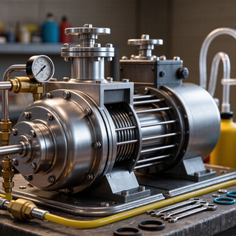
How to Choose a High Pressure Plunger Pump?
Understanding High Pressure Plunger Pump Types and Applications
High pressure plunger pumps use reciprocating plungers to create strong, controlled flow. Their design suits demanding systems that require stable pressure. Triplex pumps balance flow, efficiency, and maintenance needs for many industrial applications. Duplex pumps provide higher displacement but may produce stronger pulsation. Simplex models are easier to understand and maintain, yet their flow is less consistent. Quintuplex pumps can reduce pulsation in large, continuous-duty systems.
Application conditions should guide the choice. Water jetting needs abrasion-resistant components and reliable pressure control. Boiler feed service demands correct temperature ratings, seal materials, and clean inlet conditions. Industrial cleaning often benefits from compact triplex pumps with adjustable flow. Chemical transfer requires careful compatibility checks for plungers, packing, valves, and wetted parts. Never select pressure alone. Flow rate, duty cycle, fluid temperature, viscosity, and inlet pressure matter equally. They work together.
A practical assessment should include the actual operating point, not only the maximum rating. Add a pulsation dampener when connected equipment needs smoother flow. Check NPSH carefully, especially with long suction lines or warm fluids. Poor inlet design can damage a well-built pump. The cheapest option may look correct on paper. It may fail quietly. I would also review seal wear, access to valves, lubrication, and spare-part availability before approval. Specifications can be incomplete, and field conditions are rarely perfect.
How to Choose a High Pressure Plunger Pump?
Pressure is not the same as discharge pressure. Specify working pressure, maximum pressure, and pressure peaks separately. API Standard 674 addresses reciprocating positive-displacement pumps and pressure-related design requirements. Include startup, shutdown, bypass, and blocked-discharge conditions. Normal duty is only one slice. A relief device must match the pump’s maximum achievable pressure, not merely the process average.
Flow rate must be stated with units, temperature, and acceptable variation. Measure actual demand when possible, rather than trusting an old design sheet. A 10% margin sounds safe, but it can create unnecessary bypassing, heat, and power consumption. The U.S. Department of Energy’s Improving Pumping System Performance sourcebook reports potential energy savings of 20–50% in many pumping systems through system improvements. That figure is not a license to oversize. It is a warning to examine the whole system.
Check suction pressure, liquid temperature, viscosity, solids, and duty cycle. Confirm seal compatibility and valve response at the slowest and fastest strokes. Long suction lines can cause poor filling and damaging vibration. A neat calculation can still be wrong. I would record pressure and flow during commissioning, then compare them with the selection sheet after several operating days. If the liquid changes seasonally, reassess the pump. Small changes in viscosity or temperature may alter flow stability more than expected.
| Selection Dimension | Typical Data or Range | How to Assess the Requirement | Practical Selection Guidance |
|---|---|---|---|
| Required Discharge Pressure | 50–1,000 bar is a common range for industrial high-pressure plunger pump applications; some specialized systems operate above this range. | Determine the pressure required at the point of use, then include pressure losses through pipes, valves, filters, nozzles, and elevation changes. | Select a pump with a rated pressure above the normal operating pressure. A design margin of approximately 10–15% is commonly used when the system conditions are stable and well defined. |
| Flow Rate | Typical industrial requirements may range from 1 to 500 L/min, depending on the process and nozzle or equipment capacity. | Calculate the continuous flow required by the process. For multiple outlets, add the simultaneous flow requirements rather than the maximum flow of each outlet separately. | Choose a pump whose rated flow covers the required duty point without excessive oversizing. Oversizing can increase energy consumption, pulsation, and control difficulty. |
| Pressure–Flow Duty Point | The pump should be evaluated at the combined operating point, such as 100 L/min at 250 bar, rather than by pressure or flow alone. | Plot the required pressure and flow on the pump performance data. Confirm that the pump can maintain the required flow at the target pressure. | Do not use the maximum pressure and maximum flow ratings as if they are always available simultaneously. Confirm the manufacturer’s performance curve or rating table. |
| Hydraulic Power | Hydraulic power is calculated from pressure and flow: |
Use the approximate SI formula:
Phyd (kW) = p (bar) × Q (L/min) ÷ 600 Example: 250 bar × 100 L/min ÷ 600 = 41.7 kW. |
Motor input power must be higher than hydraulic power because of pump, drive, and transmission losses. Allow additional capacity for starting, temperature, and operating variation. |
| Pump Efficiency | Overall efficiency may commonly fall within approximately 70–90%, depending on pressure, speed, pump design, wear, and operating condition. | Compare the expected hydraulic power with the required motor input power. Volumetric efficiency decreases when internal leakage or component wear increases. | Use the efficiency value stated for the intended duty point, not only the best-case efficiency published for a different pressure or speed. |
| Fluid Type | Water, treated water, detergents, corrosion-inhibited solutions, and some compatible process fluids can be used, depending on pump materials and seals. | Identify viscosity, temperature, abrasiveness, chemical compatibility, solids content, lubricity, and gas content. | For abrasive, corrosive, flammable, or chemically aggressive fluids, verify wetted materials, packing, seals, valves, and safety requirements before selection. |
| Fluid Temperature | Many water-based applications operate around 5–60°C; higher temperatures require specifically rated seals, valves, and lubrication arrangements. | Use the maximum continuous temperature and any short-term peak temperature, not only the normal average. | High temperature can reduce seal life, lower fluid viscosity, increase vapor pressure, and raise the risk of cavitation. Confirm the allowable temperature range for every wetted component. |
| Suction Conditions and NPSH | The available NPSH must exceed the pump’s required NPSH by a suitable margin. The exact margin depends on the pump and system design. | Consider liquid temperature, suction pipe length and diameter, inlet filters, tank level, valves, dissolved gases, and vapor pressure. | Keep the suction line short and adequately sized, reduce restrictions, and avoid air leaks. A flooded suction arrangement is often preferred for reliable high-pressure operation. |
| Operating Speed | Many plunger pumps operate in the approximate range of 300–1,800 rpm, although the allowable speed depends on pump size and design. | Check the required flow, suction conditions, duty cycle, noise, vibration, and available motor or gearbox speed. | Lower speed generally reduces wear and suction demand but may require a larger pump. Never exceed the specified maximum speed or recommended acceleration rate. |
| Duty Cycle | Applications may be intermittent, such as a few hours per day, or continuous, such as 24 hours per day. | Record operating hours, start–stop frequency, standby periods, pressure changes, and expected annual running time. | For continuous service, choose components, lubrication, cooling, and maintenance intervals for the full duty cycle. An intermittent-duty pump may not be suitable for continuous operation. |
| Pulsation and Flow Smoothness | Plunger pumps produce pulsating flow. Pulsation frequency depends on the number of plungers and pump speed. | Determine whether the process requires stable pressure, accurate dosing, low vibration, or protection of downstream instruments and piping. | Use a properly sized pulsation dampener, flexible connectors, relief devices, and adequate pipe supports when a smooth flow profile is required. |
| Pressure Regulation and Protection | High-pressure systems should include a pressure relief or unloading arrangement appropriate to the maximum allowable system pressure. | Check the pump rating, hose and pipe rating, valve rating, receiver rating, and the set pressure of protective devices. | Set the relief device below the lowest-rated component in the pressure circuit. Do not rely on motor overload protection as a substitute for hydraulic overpressure protection. |
| Materials and Corrosion Resistance | Common wetted materials include stainless steel, alloy steels, ceramics, engineered polymers, and elastomers selected for the fluid. | Evaluate chloride concentration, pH, abrasive particles, chemical exposure, and cleaning agents. | Material compatibility should be checked for the complete fluid path, including plungers, manifolds, valves, seats, seals, packing, and fasteners. |
| Installation and Layout | Important factors include foundation stiffness, alignment, pipe flexibility, access clearance, ventilation, and drainage. | Review the installation drawing and confirm available space for maintenance, seal replacement, valve inspection, and lubrication service. | Prevent external pipe loads from being transferred to the pump head. Align the pump and driver accurately and provide sufficient support for high-pressure piping. |
| Noise and Vibration | Noise and vibration increase with speed, pressure pulsation, poor alignment, inadequate foundation, cavitation, and worn components. | Identify site limits for noise and vibration and consider nearby operators, instruments, structures, and sensitive equipment. | Use appropriate isolation, balanced drives, pulsation control, rigid supports, and correct alignment. Investigate unusual vibration before continued operation. |
| Maintenance Requirements | Routine tasks may include oil checks, lubrication, packing inspection, valve inspection, filter cleaning, and pressure-system testing. | Estimate acceptable downtime, maintenance skill availability, spare-parts access, and the cost of planned service. | Prefer a configuration that allows inspection and replacement of wear parts without removing the complete pump from the installation. |
| Final Selection Check | A suitable pump must satisfy pressure, flow, fluid compatibility, temperature, suction, speed, power, duty cycle, and safety requirements together. | Prepare a complete duty specification with normal, minimum, and maximum operating conditions. | Approve the selection only after confirming the full duty point, motor power, NPSH, materials, protection devices, installation limits, and maintenance plan. |
How to Choose a High Pressure Plunger Pump?
Material selection begins with the pumped fluid, not the pressure rating. Carbon steel may suit clean water, but chloride-rich fluids often demand 316L stainless steel or duplex alloys. Abrasive particles can quickly score plungers and valves. Ceramic or tungsten-carbide surfaces may extend service life, although brittle materials need careful installation. The U.S. Department of Energy’s Pumping System Sourcebook reports that pumping systems can consume 25% to 50% of industrial facility electricity. Efficient materials reduce friction, leakage, and unplanned shutdowns. Still, a stainless-steel body is not automatically a corrosion solution.
Seals require equal attention. Choose packing for easier adjustment and harsh-duty tolerance. Choose mechanical seals when leakage control and lower emissions matter. Check elastomer compatibility against temperature, chemical concentration, and pressure cycles. API 674 guidance supports reviewing fatigue, pulsation, relief protection, and pressure containment for reciprocating pumps. Triplex configurations usually provide smoother flow than simplex designs. Quintuplex arrangements can reduce pulsation further, but they increase cost and maintenance complexity. A larger pump is not always safer. Poorly matched speed can damage seals.
Tips: Confirm the fluid’s temperature, viscosity, solids content, and pH. Measure available NPSH carefully. Specify a pulsation dampener when downstream instruments need stable pressure. Leave inspection access around the seal area. In practical audits, operators often select seals first and materials later. That order can create expensive failures. Recheck assumptions with actual fluid samples, because laboratory data may not reflect field contamination.
How to Choose a High Pressure Plunger Pump?
Efficiency begins with matching the pump to the actual duty, not the highest pressure on the data sheet. Check the pump curve, flow range, motor load, and expected operating hours. A correctly sized plunger pump can deliver steady pressure without wasting power through excessive throttling. Measure the fluid temperature and viscosity, too. Small differences can change performance. Short test runs are useful, but they may hide problems that appear after several hours.
Durability depends on more than metal strength. The plunger material, packing, valves, and seals must suit the fluid and its temperature. Abrasive particles can score a plunger quickly, while poor water quality may damage valves. I have seen pumps fail early because filtration was treated as an optional accessory. It was an expensive assumption. Look for a rigid frame, balanced crank motion, and protection against dry running. A higher pressure rating is not automatically better.
Maintenance needs should be visible before installation. Choose a design with accessible inspection covers, simple lubrication points, and replaceable wear parts. Record vibration, discharge pressure, leakage, and oil condition during normal operation. These small records often reveal trouble before an unplanned shutdown. Keep critical seals and valves available, but do not replace parts on a fixed schedule without checking their condition. That approach can waste money. A practical selection leaves enough access for a technician holding tools, not just a specification sheet.
Evaluating installation, safety, and total ownership costs should guide your pump selection. Begin with the actual pressure, flow rate, fluid temperature, and operating hours. A pump that meets peak pressure may still waste energy during normal operation. Check the mounting surface, pipe alignment, inlet conditions, and available maintenance space. During field inspections, I have seen small alignment errors create noticeable vibration and seal wear. Leave room for service access. It matters.
Safety requires more than a pressure rating. Confirm that relief protection, guards, emergency shutoffs, and pressure gauges suit the complete system. Inspect hose connections and fittings before commissioning. Operators should understand startup, shutdown, lockout, and leak-response procedures. Never treat a minor leak as harmless. High-pressure fluid can penetrate skin without obvious warning. Use documented inspections, suitable protective equipment, and trained personnel.
Total ownership cost includes purchase price, electricity, spare parts, labor, downtime, and disposal. Ask how often seals, valves, and plungers need replacement under similar conditions. My early cost estimates were too optimistic because they ignored cleaning time and unplanned stoppages. That mistake changed our evaluation method. Compare energy consumption at real duty points, not only catalog figures. A slightly higher initial investment may reduce repairs, but only when the installation is correctly designed and maintained. Verify the assumptions.